Assembly
After manufacting your PyonAir PCB, you should be ready to assemble all the parts of your air pollution monitor.
Assembly steps
Choose which one of the power inputs you wish to use (barrel jack / JST / screw terminal) and connect the appropriate supply.
Use a multimeter to check the V_IN and 5V test pads on the back of the PCB. For further instructions on how to use multimeter, see Multimeter usage below.
When you're happy that the board is correctly powered, remove the power supply. (If not try alternative power supply)
Plug the LoPy4 into the 16-pin headers, ensuring the LED is at the top (as shown on the silkscreen). The bottom 4 holes in the headers are unused.
Connect each of the Grove devices into the matching sockets on the PCB.
Plug in the micro SD card.
Reconnect the power supply. The LEDs on the LoPy4 and GPS should both turn on.
Use a multimeter to check the remaining test pads on the back of the PCB.
Your PyonAir should now be ready to program!
Make sure you empty the SD card and format it as FAT32 before plugging it into the board.
Only ever connect one power source at a time. Connecting mulitple supplies at the same time could short out a battery or mains power and is very dangerous!
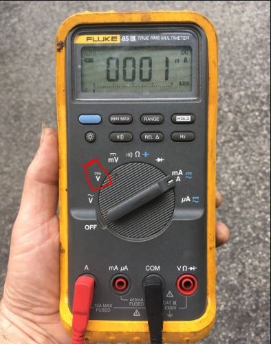
Multimeter usage
Turn the multimeter on, and turn the dial to the DC voltage symbol, highlighted with red box in image below.
Touch the black wire to the ground pad (labelled as GND) on the board (PCB) and the red wire to the 5V pad (labelled as +5V). Check that you are getting about 5V.
Last updated